Thursday 2 November 2023

Tracking Radiosondes for under $100

A really quick primer on Radiosondes, then how to track them for under $100.

What are they? 

They are a meteorological instrument which collects data on the earth’s atmosphere and transmits it back to the ground via a radio link. It is usually hanging below a latex balloon filled with helium. They are launched daily around the world by meteorological organizations to measure the weather and assist with forecasts. So the common name is a "weather balloon", as that incorporates the balloon and the instrument.

The data that they transmit depends on the brand and model, but in general, they transmit temperature, humidity and their GPS coordinates and speed, so wind speed and direction and altitude can be measured.

And, according to others that track these things, zero of these meteorological organizations try to retrieve the devices once the balloon bursts and the radiosonde drops back to the ground. So they're just disposed of. Anyone who comes across them is welcome to keep them (check local laws!)

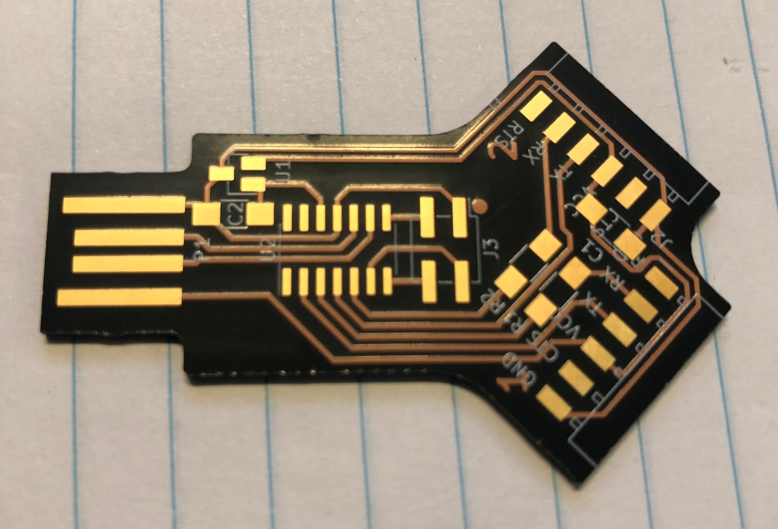
The most common one used here in Perth, Australia by the Bureau of Meteorology is the Vaisala RS41 - also called "the STM32 development board that literally falls from the sky!"

All the radiosonde's released from Perth transmit on 401.5 Mhz using FSK modulation and a data rate of 4800 baud. 

How to track a Radiosonde.

There are several ways to receive the radio transmissions from a radiosonde. The most common in recent times is using a suitable antenna, an SDR(with TCXO) and a small Linux computer (eg. Raspberry Pi). The software package Auto-RX by Mark Jessop - VK5QI runs on the Pi and uploads the received beacons to Sondehub.org . 

The Auto-RX software is actually really easy to install by following the instructions on the project GitHub wiki. I had initially tried to run the Auto-RX software on an old Orange-Pi Lite that I had lying around. This did take a while as I for some reason had to compile the SDR software from source. Unfortunately, this didn't work and kept reporting that it wouldn't get any signal from the SDR. This was possibly due to the cheap clone SDR failing and then taking out the USB port power supply.....(nothing was working via that port)

I tried again using an Orange Pi Zero (with Allwinner H2+ processor) using an Armbian Bullseye OS image, then installed Auto-RX using the Docker method. I used an older Nooelec SDR this time round. It did work briefly, but then stopped after a day or two. I think this was due to something overheating, but when I removed the SDR and rebooted the Orange Pi, it wouldn't connect to the wireless network at all. Rather than troubleshoot and buy another replacement SDR, I decided it's time for a different approach.

Enter the TTGO/LilyGo T-Beam V1.1 , This is a small module based on the ESP32 WiFi/Bluetooth Microcontroller. The module includes a 433Mhz ISM transceiver that is based on the Semtech SX1278 IC. It also has a GPS receiver, a 18650 li-ion battery holder and associated charging circuitry, and optionally, a small 0.96" OLED screen. 

The trick here is the firmware developed by DL9RDZ (and others) - "rdzTTGOsonde". Rather than having an SDR that is a universal radio receiver, the SX1278 RF module onboard the T-Beam is controlled by the firmware on the ESP32, which incorporates a limited set of decoders for common Radiosonde models - including the Vaisala RS41 that is used locally. As the module has Wifi onboard, any detected and decoded beacons are automatically uploaded to a variety of web-based services, including Sondehub.org. The firmware supports a number of ESP32-based boards, including the T-Beam and the cheaper and more common TTGO LoRa32 2.1_1.6 board (with no GPS onboard)

The easiest way to install the firmware was to first download the precompiled .bin file from the projects github pag, then download the Espressif ESP32 Flash Download Tool. Following the instructions from the link in the wiki, the firmware was uploaded with minimal issues. The screenshots in the link do need updating to match the current version (3.9.5) of the tool. 

Once the firmware was loaded and the board reset, I connected to the SoftAP of the device, entered my local wifi settings, then rebooted again. I could now access it via my local network. I logged into the web page onboard the T-Beam and added the required configuration settings, such as the frequency of the local Radiosondes, turned on the upload to Sondehub.org and set my Amateur Radio callsign.

For some reason, I didn't receive any beacons during the next Radiosonde Launch. This was checked using the SondeHub website. The local airport releases 2 balloons per day on a fairly consistent schedule. The station was shown to be online, but no Radio signal????

I then tried out the OTA firmware update feature. I selected the Development branch this time round. After the device automatically rebooted, I logged back in and check all the settings were still there. Yes! Now to wait for the next balloon release. Finally, I had success!!! The station was receiving the beacons with a simple magnetic monopole antenna on the roof of my patio!

In hindsight, if I'd read the release notes for the Development Branch firmware, I would have discovered earlier that the T-Beam V1.1 (not V1.0) had a different power management chip (AXP2101), and the release on Aug 28, 2023 was the first one that contained the required code to support this chip and therefore power up the radio transceiver properly. 

The T-Beam V1.1 (available in regular or Meshtastic pre-loaded firmware) currently costs between $55 and $65 AUD. The antenna is a Dual Band VHF/UHF monopole antenna - UT-106UV, and costs under $9AUD. So for $74AUD (currently approx $47USD), and a USB power supply, you too can track the STM32 Dev boards that fall from the sky!

Note - Cheaper still is the Lora32 at $33AUD. Same performance for under $50AUD! (but no chase car functionality if you're trying to track down a radiosonde.)


Saturday 21 October 2023

Time Flies

I finally logged back into the blog and saw my last post was over 6 years ago! Life in general has been busy and sometimes hobbies have to take a back seat for a while. After 6 years, it's interesting to see how picosatellite development and the tech world has changed, but also how some things haven't changed.

I had drafted some posts that I never got round to finishing and publishing online. It may have been that I hadn't finished my musing on that topic and it needed more content. Maybe I'll re-read and see if my thinking has changed...

The OzQube-1 project is still alive, but not very active. As a tech demonstrator, I hadn't found a way for it to provide any direct commercial benefit, aside from gaining space heritage and proving out the platform, ready for a larger, more capable PocketQube that would have been developed though my company - Picosat Systems. Plus, as I said before, life has become too busy to spend any significant time on the project or the Picosat Systems company. In fact, the co-founder of the company and I have agreed to wind it up this year, as we're both not able to put in the time and resources that a start-up needs.

Where to now?

Once and engineer, always an engineer (except I'm not officially an engineer!)- but you know what I mean. I have the engineering mindset or way of thinking. There's always something to tinker with. Here's one of the projects that I did find time for.

During the COVID pandemic in 2020 and the "Great Electronic Parts Shortage" that ensued, the most common microcontrollers were out of stock everywhere. However, I did manage to purchase a few bits and pieces that I thought would be interesting and that I could do some projects with.  

One of these components was the Microchip (Atmel) SAMD11C14 . I saw a post on Hackaday that got me intrigued. I found some other Hackaday.io projects using it as well.

It's a 14 pin, ARM Cortex M0+, with 16kb of flash and 4kb of SRAM. Nothing exceptional. But it does have a USB Full Speed interface and doesn't require a crystal to run it. Which means that a device can be build with minimal components. Luckily for me, in 2020, Quentin Bolsee enrolled in FabAcademy and developed a number of projects using this chip. One of these projects was a small USB to dual serial port adapter. The key feature of this adapter was that it could be a UPDI programmer for an AVR, while also communicating on the serial port. 

Now, while I had purchased the IC itself, I didn't pay much attention to the other components. I figured I would have something lying around that could be used for the other few parts (this comes back to bite me later!) The original PCB was milled from FR4, but I literally just grabbed the Gerbers that were uploaded to the FabAcademy site, and uploaded them to OshPark for manufacturing. I chose the "After Dark" PCB, because it looks cool, and being able to see the traces would pay tribute to the original milled version. 

Once the PCBs arrived, I set out to assemble them. I had a bunch of components in an old SeeedStudio Open Parts Library kit that I'd acquired in 2015. 

 I figured this would have all that I needed. (WRONG!) I started with the 6 pin connectors. They were straight, and would have shorted the traces in the milled version, but luckily there's clear solder mask on my version. But to be safe, I bent the pins so that they were slightly raised above the pcb surface. Next issue was the resistors. The OPL kit had a few 0805 components that I thought would fit. No. Not really. They all seemed too small! It turns out the passives in this project were all 1206!! Who uses 1206 resistors??? ( People who mill PCBs, that's who). I managed to bodge the 0805 resistors and capacitors in place with a generous blob of solder. The 4 pin programming header was a surface mount component. If you don't have one of these lying round, just bend the pins outwards on a through hole header so that they're flat! Ta-Da!! Surface mount header. 

Now for the only other component aside from the microcontroller. The LDO voltage regulator. The SeeedStudio kit had a suitable one right? Yep. 3.3v output. 3 pin SOT-23. Soldered that on, then the IC, then put some thick blobs where the USB connector traces are, as a 1.6mm PCB isn't thick enough on its own to be a USB plug. 


Now for the moment of truth.......plug it in to power and check everything with the multimeter..... NOPE! No 3.3v supply. Hmmm. I'd better look at the components they used using the supplied Kicad project. Oh look -  It's an LM3480 LDO, that's out of stock everywhere. Looking closer, the LM3480 uses the pinout 1- Out, 2 - In, 3- GND. Which other LDO uses this pinout? None that were easily found. There are variations that had the ins and outs swapped, ones that had the GND on a different pin, but nothing that matched the LM3480. In the end, I ordered an AP7333, but when it was time to solder it in, I needed to bend the pins the opposite way and solder it in upside down. This actually works a treat. As I had to order parts, I also ordered 1206 components so that my three PCBs would look normal and soler much more easily. And proper surface mount programming headers and output header sockets. 

Once the parts arrived, I re-assembled the first board with properly sized resistors and capacitors, turned the LDO upside down, bent the pins down and soldered into place. Then I plugged back into a USB power supply to test with the multimeter again. Success!!!! 3.3V supply in the right places. 


The last step was to program the SAMD11C4. The 4 pins are a SWD connector. While waiting for PCBs and parts for this project, I decided to buy myself a proper(ish) programmer/debugger and bought an MPLAB SNAP programmer. I figured I could use this to program these adapters. I connected the 4 wires - RST(MCLR on the SNAP), SWCLK, SWDIO and GND, and plugged the adapter into a usb power supply. Quentin's project page had the BIN file to upload directly. There was a very brief paragraph that said I needed to just "flash with edbg". Simple right? No, seems the MPLAB SNAP isn't recognised in Microchip (Atmel) Studio 7. I would have to use Microchip MPLAB X IDE. I imported the Studio project then proceeded to build and upload. Fail. Errors during the build. It had something to do with the source file location and names. Sounded like alot of troubleshooting that I wasn't keen on trying right now. Then I discovered that the ZIP of the project included the various HEX, ELF and other output files in the Release directory. The MPLAB X IDA can import HEX files, so I then imported the HEX file into new project in MPLAB X. Then I hit the "Make and Program Device" button and watched the output console. FAIL. The process stopped after detecting the SNAP debugger.

I went back to the SNAP manual, and it seemed like for an SWD connection, the SNAP needed to have another pin connected - the VTG pin, or Voltage Target? Not having any spare pins on the programming header, I literally just held a wire against the 3.3v output of the LDO, then clicked the Program Device button. 

SUCCESS!!! SAMD11C14 detected and programmed.

I plugged the adapter into the computer and as per the design - 2 serial ports were detected!

Now I have 3 dual serial port adapters for programming and connecting to the other chips I managed to find during the Great Parts Shortage - some AVR128DB64 microcontrollers. The plan is to load the Arduino bootloader onto them using DxCore from Spence Konde (aka Dr. Azzy). These new AVRs have 16KB SRAM, 128KB of flash, 512bytes EEPROM, plus a bunch of other integrated peripherals that were very appealing.