I finally logged back into the blog and saw my last post was over 6 years ago! Life in general has been busy and sometimes hobbies have to take a back seat for a while. After 6 years, it's interesting to see how picosatellite development and the tech world has changed, but also how some things haven't changed.
I had drafted some posts that I never got round to finishing and publishing online. It may have been that I hadn't finished my musing on that topic and it needed more content. Maybe I'll re-read and see if my thinking has changed...
The OzQube-1 project is still alive, but not very active. As a tech demonstrator, I hadn't found a way for it to provide any direct commercial benefit, aside from gaining space heritage and proving out the platform, ready for a larger, more capable PocketQube that would have been developed though my company - Picosat Systems. Plus, as I said before, life has become too busy to spend any significant time on the project or the Picosat Systems company. In fact, the co-founder of the company and I have agreed to wind it up this year, as we're both not able to put in the time and resources that a start-up needs.
Where to now?
Once and engineer, always an engineer (except I'm not officially an engineer!)- but you know what I mean. I have the engineering mindset or way of thinking. There's always something to tinker with. Here's one of the projects that I did find time for.
During the COVID pandemic in 2020 and the "Great Electronic Parts Shortage" that ensued, the most common microcontrollers were out of stock everywhere. However, I did manage to purchase a few bits and pieces that I thought would be interesting and that I could do some projects with.
One of these components was the Microchip (Atmel) SAMD11C14 . I saw a post on Hackaday that got me intrigued. I found some other Hackaday.io projects using it as well.
It's a 14 pin, ARM Cortex M0+, with 16kb of flash and 4kb of SRAM. Nothing exceptional. But it does have a USB Full Speed interface and doesn't require a crystal to run it. Which means that a device can be build with minimal components. Luckily for me, in 2020, Quentin Bolsee enrolled in FabAcademy and developed a number of projects using this chip. One of these projects was a small USB to dual serial port adapter. The key feature of this adapter was that it could be a UPDI programmer for an AVR, while also communicating on the serial port.
Now, while I had purchased the IC itself, I didn't pay much attention to the other components. I figured I would have something lying around that could be used for the other few parts (this comes back to bite me later!) The original PCB was milled from FR4, but I literally just grabbed the Gerbers that were uploaded to the FabAcademy site, and uploaded them to OshPark for manufacturing. I chose the "After Dark" PCB, because it looks cool, and being able to see the traces would pay tribute to the original milled version.
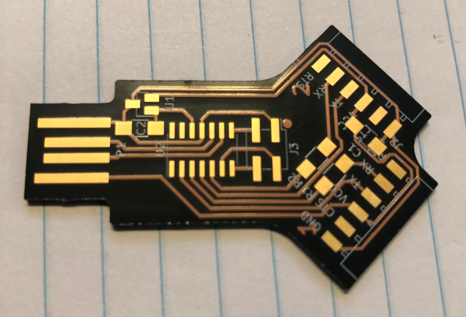
Once the PCBs arrived, I set out to assemble them. I had a bunch of components in an old SeeedStudio Open Parts Library kit that I'd acquired in 2015.
I figured this would have all that I needed. (WRONG!) I started with the 6 pin connectors. They were straight, and would have shorted the traces in the milled version, but luckily there's clear solder mask on my version. But to be safe, I bent the pins so that they were slightly raised above the pcb surface. Next issue was the resistors. The OPL kit had a few 0805 components that I thought would fit. No. Not really. They all seemed too small! It turns out the passives in this project were all 1206!! Who uses 1206 resistors??? ( People who mill PCBs, that's who). I managed to bodge the 0805 resistors and capacitors in place with a generous blob of solder. The 4 pin programming header was a surface mount component. If you don't have one of these lying round, just bend the pins outwards on a through hole header so that they're flat! Ta-Da!! Surface mount header.
Now for the only other component aside from the microcontroller. The LDO voltage regulator. The SeeedStudio kit had a suitable one right? Yep. 3.3v output. 3 pin SOT-23. Soldered that on, then the IC, then put some thick blobs where the USB connector traces are, as a 1.6mm PCB isn't thick enough on its own to be a USB plug.


Once the parts arrived, I re-assembled the first board with properly sized resistors and capacitors, turned the LDO upside down, bent the pins down and soldered into place. Then I plugged back into a USB power supply to test with the multimeter again. Success!!!! 3.3V supply in the right places.

The last step was to program the SAMD11C4. The 4 pins are a SWD connector. While waiting for PCBs and parts for this project, I decided to buy myself a proper(ish) programmer/debugger and bought an MPLAB SNAP programmer. I figured I could use this to program these adapters. I connected the 4 wires - RST(MCLR on the SNAP), SWCLK, SWDIO and GND, and plugged the adapter into a usb power supply. Quentin's project page had the BIN file to upload directly. There was a very brief paragraph that said I needed to just "flash with edbg". Simple right? No, seems the MPLAB SNAP isn't recognised in Microchip (Atmel) Studio 7. I would have to use Microchip MPLAB X IDE. I imported the Studio project then proceeded to build and upload. Fail. Errors during the build. It had something to do with the source file location and names. Sounded like alot of troubleshooting that I wasn't keen on trying right now. Then I discovered that the ZIP of the project included the various HEX, ELF and other output files in the Release directory. The MPLAB X IDA can import HEX files, so I then imported the HEX file into new project in MPLAB X. Then I hit the "Make and Program Device" button and watched the output console. FAIL. The process stopped after detecting the SNAP debugger.
I went back to the SNAP manual, and it seemed like for an SWD connection, the SNAP needed to have another pin connected - the VTG pin, or Voltage Target? Not having any spare pins on the programming header, I literally just held a wire against the 3.3v output of the LDO, then clicked the Program Device button.
SUCCESS!!! SAMD11C14 detected and programmed.
I plugged the adapter into the computer and as per the design - 2 serial ports were detected!
Now I have 3 dual serial port adapters for programming and connecting to the other chips I managed to find during the Great Parts Shortage - some AVR128DB64 microcontrollers. The plan is to load the Arduino bootloader onto them using DxCore from Spence Konde (aka Dr. Azzy). These new AVRs have 16KB SRAM, 128KB of flash, 512bytes EEPROM, plus a bunch of other integrated peripherals that were very appealing.