Thursday 2 November 2023

Tracking Radiosondes for under $100

A really quick primer on Radiosondes, then how to track them for under $100.

What are they? 

They are a meteorological instrument which collects data on the earth’s atmosphere and transmits it back to the ground via a radio link. It is usually hanging below a latex balloon filled with helium. They are launched daily around the world by meteorological organizations to measure the weather and assist with forecasts. So the common name is a "weather balloon", as that incorporates the balloon and the instrument.

The data that they transmit depends on the brand and model, but in general, they transmit temperature, humidity and their GPS coordinates and speed, so wind speed and direction and altitude can be measured.

And, according to others that track these things, zero of these meteorological organizations try to retrieve the devices once the balloon bursts and the radiosonde drops back to the ground. So they're just disposed of. Anyone who comes across them is welcome to keep them (check local laws!)

The most common one used here in Perth, Australia by the Bureau of Meteorology is the Vaisala RS41 - also called "the STM32 development board that literally falls from the sky!"

All the radiosonde's released from Perth transmit on 401.5 Mhz using FSK modulation and a data rate of 4800 baud. 

How to track a Radiosonde.

There are several ways to receive the radio transmissions from a radiosonde. The most common in recent times is using a suitable antenna, an SDR(with TCXO) and a small Linux computer (eg. Raspberry Pi). The software package Auto-RX by Mark Jessop - VK5QI runs on the Pi and uploads the received beacons to Sondehub.org . 

The Auto-RX software is actually really easy to install by following the instructions on the project GitHub wiki. I had initially tried to run the Auto-RX software on an old Orange-Pi Lite that I had lying around. This did take a while as I for some reason had to compile the SDR software from source. Unfortunately, this didn't work and kept reporting that it wouldn't get any signal from the SDR. This was possibly due to the cheap clone SDR failing and then taking out the USB port power supply.....(nothing was working via that port)

I tried again using an Orange Pi Zero (with Allwinner H2+ processor) using an Armbian Bullseye OS image, then installed Auto-RX using the Docker method. I used an older Nooelec SDR this time round. It did work briefly, but then stopped after a day or two. I think this was due to something overheating, but when I removed the SDR and rebooted the Orange Pi, it wouldn't connect to the wireless network at all. Rather than troubleshoot and buy another replacement SDR, I decided it's time for a different approach.

Enter the TTGO/LilyGo T-Beam V1.1 , This is a small module based on the ESP32 WiFi/Bluetooth Microcontroller. The module includes a 433Mhz ISM transceiver that is based on the Semtech SX1278 IC. It also has a GPS receiver, a 18650 li-ion battery holder and associated charging circuitry, and optionally, a small 0.96" OLED screen. 

The trick here is the firmware developed by DL9RDZ (and others) - "rdzTTGOsonde". Rather than having an SDR that is a universal radio receiver, the SX1278 RF module onboard the T-Beam is controlled by the firmware on the ESP32, which incorporates a limited set of decoders for common Radiosonde models - including the Vaisala RS41 that is used locally. As the module has Wifi onboard, any detected and decoded beacons are automatically uploaded to a variety of web-based services, including Sondehub.org. The firmware supports a number of ESP32-based boards, including the T-Beam and the cheaper and more common TTGO LoRa32 2.1_1.6 board (with no GPS onboard)

The easiest way to install the firmware was to first download the precompiled .bin file from the projects github pag, then download the Espressif ESP32 Flash Download Tool. Following the instructions from the link in the wiki, the firmware was uploaded with minimal issues. The screenshots in the link do need updating to match the current version (3.9.5) of the tool. 

Once the firmware was loaded and the board reset, I connected to the SoftAP of the device, entered my local wifi settings, then rebooted again. I could now access it via my local network. I logged into the web page onboard the T-Beam and added the required configuration settings, such as the frequency of the local Radiosondes, turned on the upload to Sondehub.org and set my Amateur Radio callsign.

For some reason, I didn't receive any beacons during the next Radiosonde Launch. This was checked using the SondeHub website. The local airport releases 2 balloons per day on a fairly consistent schedule. The station was shown to be online, but no Radio signal????

I then tried out the OTA firmware update feature. I selected the Development branch this time round. After the device automatically rebooted, I logged back in and check all the settings were still there. Yes! Now to wait for the next balloon release. Finally, I had success!!! The station was receiving the beacons with a simple magnetic monopole antenna on the roof of my patio!

In hindsight, if I'd read the release notes for the Development Branch firmware, I would have discovered earlier that the T-Beam V1.1 (not V1.0) had a different power management chip (AXP2101), and the release on Aug 28, 2023 was the first one that contained the required code to support this chip and therefore power up the radio transceiver properly. 

The T-Beam V1.1 (available in regular or Meshtastic pre-loaded firmware) currently costs between $55 and $65 AUD. The antenna is a Dual Band VHF/UHF monopole antenna - UT-106UV, and costs under $9AUD. So for $74AUD (currently approx $47USD), and a USB power supply, you too can track the STM32 Dev boards that fall from the sky!

Note - Cheaper still is the Lora32 at $33AUD. Same performance for under $50AUD! (but no chase car functionality if you're trying to track down a radiosonde.)
Saturday 21 October 2023

Time Flies

I finally logged back into the blog and saw my last post was over 6 years ago! Life in general has been busy and sometimes hobbies have to take a back seat for a while. After 6 years, it's interesting to see how picosatellite development and the tech world has changed, but also how some things haven't changed.

I had drafted some posts that I never got round to finishing and publishing online. It may have been that I hadn't finished my musing on that topic and it needed more content. Maybe I'll re-read and see if my thinking has changed...

The OzQube-1 project is still alive, but not very active. As a tech demonstrator, I hadn't found a way for it to provide any direct commercial benefit, aside from gaining space heritage and proving out the platform, ready for a larger, more capable PocketQube that would have been developed though my company - Picosat Systems. Plus, as I said before, life has become too busy to spend any significant time on the project or the Picosat Systems company. In fact, the co-founder of the company and I have agreed to wind it up this year, as we're both not able to put in the time and resources that a start-up needs.

Where to now?

Once and engineer, always an engineer (except I'm not officially an engineer!)- but you know what I mean. I have the engineering mindset or way of thinking. There's always something to tinker with. Here's one of the projects that I did find time for.

During the COVID pandemic in 2020 and the "Great Electronic Parts Shortage" that ensued, the most common microcontrollers were out of stock everywhere. However, I did manage to purchase a few bits and pieces that I thought would be interesting and that I could do some projects with.  

One of these components was the Microchip (Atmel) SAMD11C14 . I saw a post on Hackaday that got me intrigued. I found some other Hackaday.io projects using it as well.

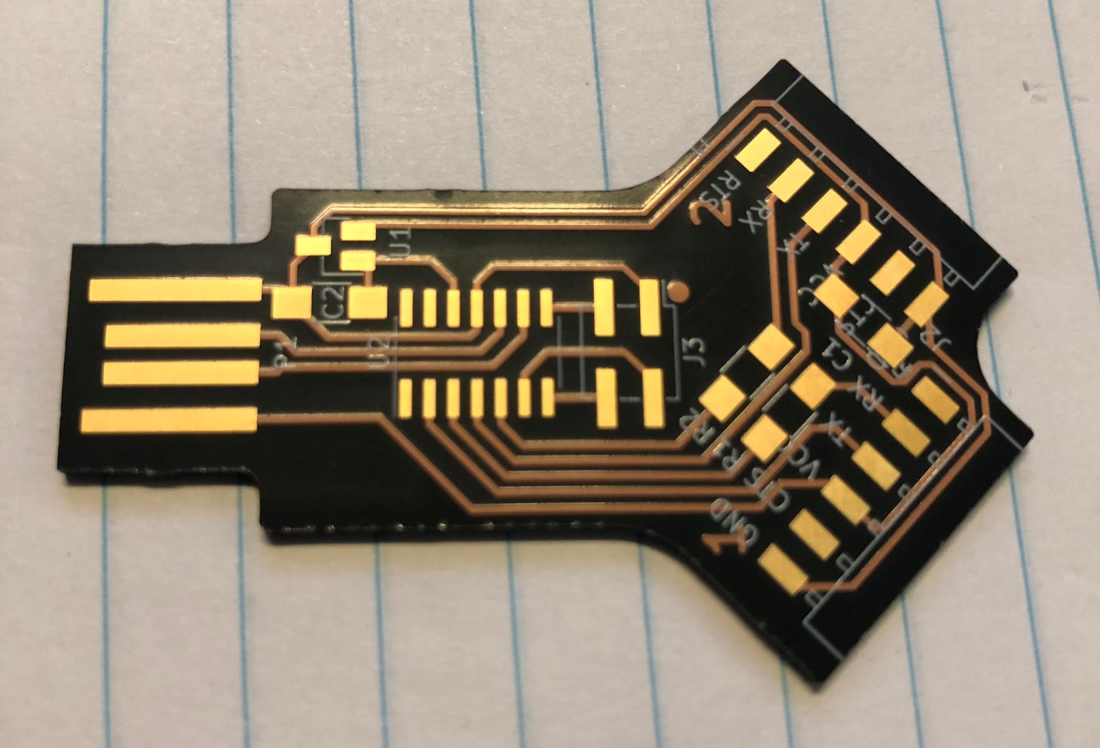
It's a 14 pin, ARM Cortex M0+, with 16kb of flash and 4kb of SRAM. Nothing exceptional. But it does have a USB Full Speed interface and doesn't require a crystal to run it. Which means that a device can be build with minimal components. Luckily for me, in 2020, Quentin Bolsee enrolled in FabAcademy and developed a number of projects using this chip. One of these projects was a small USB to dual serial port adapter. The key feature of this adapter was that it could be a UPDI programmer for an AVR, while also communicating on the serial port. 

Now, while I had purchased the IC itself, I didn't pay much attention to the other components. I figured I would have something lying around that could be used for the other few parts (this comes back to bite me later!) The original PCB was milled from FR4, but I literally just grabbed the Gerbers that were uploaded to the FabAcademy site, and uploaded them to OshPark for manufacturing. I chose the "After Dark" PCB, because it looks cool, and being able to see the traces would pay tribute to the original milled version. 

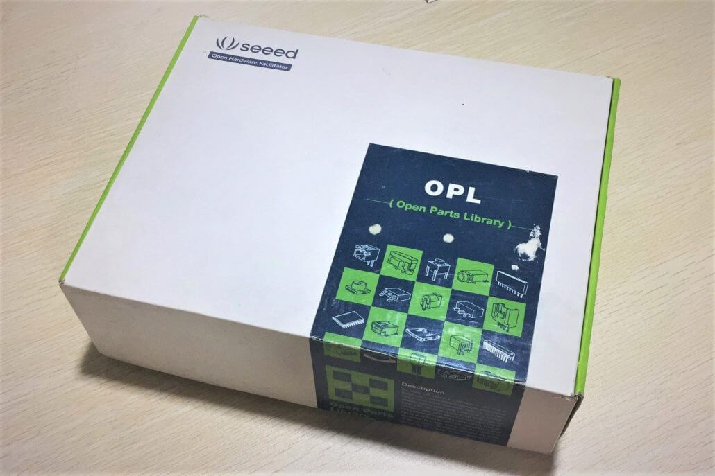
Once the PCBs arrived, I set out to assemble them. I had a bunch of components in an old SeeedStudio Open Parts Library kit that I'd acquired in 2015. 

 I figured this would have all that I needed. (WRONG!) I started with the 6 pin connectors. They were straight, and would have shorted the traces in the milled version, but luckily there's clear solder mask on my version. But to be safe, I bent the pins so that they were slightly raised above the pcb surface. Next issue was the resistors. The OPL kit had a few 0805 components that I thought would fit. No. Not really. They all seemed too small! It turns out the passives in this project were all 1206!! Who uses 1206 resistors??? ( People who mill PCBs, that's who). I managed to bodge the 0805 resistors and capacitors in place with a generous blob of solder. The 4 pin programming header was a surface mount component. If you don't have one of these lying round, just bend the pins outwards on a through hole header so that they're flat! Ta-Da!! Surface mount header. 

Now for the only other component aside from the microcontroller. The LDO voltage regulator. The SeeedStudio kit had a suitable one right? Yep. 3.3v output. 3 pin SOT-23. Soldered that on, then the IC, then put some thick blobs where the USB connector traces are, as a 1.6mm PCB isn't thick enough on its own to be a USB plug. 


Now for the moment of truth.......plug it in to power and check everything with the multimeter..... NOPE! No 3.3v supply. Hmmm. I'd better look at the components they used using the supplied Kicad project. Oh look -  It's an LM3480 LDO, that's out of stock everywhere. Looking closer, the LM3480 uses the pinout 1- Out, 2 - In, 3- GND. Which other LDO uses this pinout? None that were easily found. There are variations that had the ins and outs swapped, ones that had the GND on a different pin, but nothing that matched the LM3480. In the end, I ordered an AP7333, but when it was time to solder it in, I needed to bend the pins the opposite way and solder it in upside down. This actually works a treat. As I had to order parts, I also ordered 1206 components so that my three PCBs would look normal and soler much more easily. And proper surface mount programming headers and output header sockets. 

Once the parts arrived, I re-assembled the first board with properly sized resistors and capacitors, turned the LDO upside down, bent the pins down and soldered into place. Then I plugged back into a USB power supply to test with the multimeter again. Success!!!! 3.3V supply in the right places. 


The last step was to program the SAMD11C4. The 4 pins are a SWD connector. While waiting for PCBs and parts for this project, I decided to buy myself a proper(ish) programmer/debugger and bought an MPLAB SNAP programmer. I figured I could use this to program these adapters. I connected the 4 wires - RST(MCLR on the SNAP), SWCLK, SWDIO and GND, and plugged the adapter into a usb power supply. Quentin's project page had the BIN file to upload directly. There was a very brief paragraph that said I needed to just "flash with edbg". Simple right? No, seems the MPLAB SNAP isn't recognised in Microchip (Atmel) Studio 7. I would have to use Microchip MPLAB X IDE. I imported the Studio project then proceeded to build and upload. Fail. Errors during the build. It had something to do with the source file location and names. Sounded like alot of troubleshooting that I wasn't keen on trying right now. Then I discovered that the ZIP of the project included the various HEX, ELF and other output files in the Release directory. The MPLAB X IDA can import HEX files, so I then imported the HEX file into new project in MPLAB X. Then I hit the "Make and Program Device" button and watched the output console. FAIL. The process stopped after detecting the SNAP debugger.

I went back to the SNAP manual, and it seemed like for an SWD connection, the SNAP needed to have another pin connected - the VTG pin, or Voltage Target? Not having any spare pins on the programming header, I literally just held a wire against the 3.3v output of the LDO, then clicked the Program Device button. 

SUCCESS!!! SAMD11C14 detected and programmed.

I plugged the adapter into the computer and as per the design - 2 serial ports were detected!

Now I have 3 dual serial port adapters for programming and connecting to the other chips I managed to find during the Great Parts Shortage - some AVR128DB64 microcontrollers. The plan is to load the Arduino bootloader onto them using DxCore from Spence Konde (aka Dr. Azzy). These new AVRs have 16KB SRAM, 128KB of flash, 512bytes EEPROM, plus a bunch of other integrated peripherals that were very appealing.  


Sunday 15 January 2017

Getting to Blinky - With a STM32 "Blue Pill" devboard

For the newbie embedded developer, the Arduino ecosystem is the perfect place to start. It's really easy to get up and running with a new development board. All you have to do is buy one of the branded boards, like an Arduino/Genuino Uno, download and install the single software package, then run the IDE. All the required drivers are installed and the interface, while fairly spartan, is easy to use. Just select the board type and load one of the example pieces of code.

The popularity of the Arduino ecosystem of software and dev board hardware, along with its open source heart, has meant that a range of clones or compatible products are also available. This means that you can buy a really cheap development board from places like eBay or AliExpress. Even though Arduino hardware started with 8 Bit Atmel ATMega microcontrollers, they have now evolved to include a range of modern 32 bit microcontrollers, like the Atmel (now Microchip) SAMD21 in the Arduino Zero. Others have adapted the Arduino IDE to be used with a variety of hardware, like the really cheap WiFi chip ESP8266. This proved very popular with tinkerers the world over, so much so that the newer version of the Arduino software included support to be able to run code directly on these little modules. This required someone to adapt the Arduino bootloader to the chip. The "bootloader" is a little piece of code that runs when the device first boots up, providing a mechanism for people to load custom code onto the chip using a simple serial protocol.

One of the simplest and smallest 8-bit Arduino modules is the Pro Mini. It requires an external USB to UART adapter in order to program it. Sparkfun Electronics designed it as a module to be included in electronics projects. It's only $10USD, although it's more like $20AUD by the time it gets here. plus you need the USB to UART adapter, which at $15USD costs more than the dev board itself!! So even trying to do it cheaply, here in Australia you're looking at something around $40, which is about the cost of the UNO board that includes the communication IC.

I use the 3.3V version of the Pro Mini in several projects, because many (most) sensors these days only speak at a 3.3v level. If you use the usual 5V Arduino, you need things like "level shifters" to make sure the voltage level of the signalling circuit doesn't fry the expensive sensor. Instead of spending alot of cash mucking around with the brand name boards, you can buy cheap clones of these from Aliexpress, so it's really easy to leave these inside whatever project you're making, and not worry if it gets zapped or blown up. Sure, there are some issues using these instead of the proper branded ones, but sometimes cash is king. The lowest cost often wins!

 But how cheap? Try around $2 a piece!

But what if you need something more powerful, like one of these 32 bit Arduinos? The Arduino branded ones with the 32bit microcontroller still cost around the same as the 8-bit ones, but most of them incorporate a USB interface on the chip, removing the need to have any external programming board. So what cheap 32 bit option is there?

It turns out that there aren't many clones of 32 bit Arduino devices. But China does have an equivalent to the Pro Mini. It's often called a "STM32 Minimum System Development Board", or a "Red Pill" or "Blue Pill" depending on the PCB colour. It uses a STM32F103 microcontroller, and has a breadboard friendly form factor. I first read about it on the CNX Software blog . It can be loaded with a modified bootloader so that it can be programmed using the Arduino IDE. Given the cost was so low, I thought I'd buy one and have a tinker. Proper embedded developers use a hardware debug tool to program similar hardware, so I bought a cheap one of these to match. I didn't know if I'd need it, but I figured it was cheap enough to have on hand if I ever needed it.
STM32F103 Blue Pill board and ST-LINK V2 debug tool


Enough of the background story. I ended up trying a few things before I finally managed to get the onboard LED to obey my flashing commands!!! Here's a summary of the process.


  1. Download and install the latest Arduino IDE. Currently 
  2. Turns out that the ST-LINK V2 dongle IS useful. Rather than just install the drivers for it that can be sourced from the ST website, download the entire "ST-LINK Utility", which includes the driver AND relevant application. Run the installer and follow the prompts.
  3. Download the STM32-duino bootloader repository. Save and extract it to a temporary location. Thanks to Roger Clarke for making the mods to suit the STM32F103 boards!
  4. I probably did this step wrong, but in the end it seemed to work. The instructions for this step are here. Roger Clarke has another Github repo for all the board hardware files, so that the STM32F103 and others can work with the Arduino IDE. Follow the instructions and download and extract the repo into the correct location. If this doesn't work, and you have the latest version of Arduino with the "Boards Manager", instead of downloading the repo,  just add "http://dan.drown.org/stm32duino/package_STM32duino_index.json" as an additional boards manager url in the IDE preferences. Restart the IDE, then go to the Boards Manager (Tools > Board:xxxx > Boards Manager). Scroll to the bottom of the list and you should find the one labelled "STM32F1XX/GD32F1XX boards by stm32duino". Click the name, then click the Install button that appears. Wait for it to download and install, then restart the IDE for good measure.
At this point, you should be able to select the "Generic STM32F103C series board, then select the "STM32F103C8 (20k RAM. 64k Flash)" variant, and the CPU speed of 72Mhz. You then need to connect the ST-LINK V2 to the dev board. The end connectors opposite the Micro-USB socket are the ones to connect. From top to bottom, the pins are labelled "GND, SWCLK, SWDIO, and 3.3". On mine, the SW is hidden by the pin header.

Connect these to the corresponding 4 pins on the bottom row of the ST-LINK tool. The case shows the pinout. Make sure you plug the power into 3.3V, not the 5V pin. You can then plug the ST-LINK into your computers USB port. Back in the Arduino IDE, in the "Tools" menu, choose "SWD" as the upload method. Now you can write some code, or choose one of the examples in the "Generic STM32F103 series" section.

In my case, the onboard LED is marked as being connected to the pin PC13. I used this name as the reference in the Blink example, and voila!!! Flashing LED.

Now if you don't want to use the ST-LINK, and just want to use the onboard Micro-USB port, then you'll need to install the bootloader. First, make sure the dev board is wired up to the ST-LINK as before. On your computer, run the "STM32 ST-LINK utility". Click "Target" then "Connect". Information should appear in the "Device" area at the top right of the window - like this:

Then click File > Open File, and navigate to the extracted bootloader files you downloaded at step 3. Navigate into the folder named "binaries", and find the file named "generic_boot20_pc13.bin". This is because the LED is on PC13!! Then click "Target" then "Program". In the next window, ensure the 
start address is "0x08000000", then click "Start". Wait about 4 seconds til it's finished, then you're almost there. The last step is to install the DFU utilities that were part of the download in step 4. Inside the extracted ZIP of the Github repo, navigate to "\Arduino_STM32\tools\win\dfu-util-0.9-win64\" folder, and run the "dfu-util.exe" program. This will install the drivers for the "Maple Serial" device, and the DFU driver. DFU means "Device Firmware Update". It's a mode where firmware can be loaded from an external source. 

Now in the Arduino IDE, you need to select the upload method of "STM32duino bootloader". Write some more code, then click upload......and nothing happens!! But it says "Done Uploading" ???
With this board, you need to press the reset button just after the IDE shows that it is uploading, otherwise the process will timeout and fail. Try uploading again, and press reset at the right time.

Well done! You've got to Blinky 2 ways - via SWD and via the STM32duino bootloader!


Sunday 7 February 2016

#SocialSpaceWA - ESA's First Western Australian SocialSpace event!

BACKGROUND

When you hear "European Space Agency Deep Space Tracking Station," it's understandable that the first thing you think of is that it's somewhere in Europe. While there is a station located in Europe, the ESA actually has two other deep space antennas equally spaced around the world as part of their Estrack network. Estrack is a global system of ground stations providing links between satellites in orbit and ESOC, the European Space Operations Centre, Darmstadt, Germany.

 Deep Space Antenna 1 (DSA 1) is located in New Norcia, Western Australia. It was commissioned in 2002 and was the first antenna in ESA's Deep Space Network, which was designed to give the ESA an independent  capability to communicate and control deep space missions. It is a huge 35m diameter parabolic dish, with the capability to communicate beyond Mars. The first signals received by this station were from the NASA Stardust mission in June 2002.
DSA 2 is located 77 kms west of Madrid, Spain, at a place called Cebreros. Like DSA 1, the dish in Spain is a 35m diameter. It is separated from DSA 1 by 120 degrees of longitude, and was first commissioned in 2005
DSA 3 is another 120 degrees around the globe, at Malargüe, Argentina. It began operation in 2012.

The three Deep Space Antennas complement the NASA Deep Space Network, giving a combined total of 6 stations. Three in the Northern Hemisphere, and 3 in the Southern Hemisphere.

Estrack have a number of other resources in Western Australia. Up until 2015, there was a station located on the outskirts of the state capital - Perth. This was used to communicate to satellites in Low Earth Orbit, as well as other spacecraft during their Launch and Early Orbit Phase (LEOP). This station was recently decommissioned, with the functionality taken over by a new 4.5m dish out at New Norcia - 120km away. Which is the reason for this blog post!!! ( Finally....)

#SocialSpaceWA

Only a few weeks ago, I saw that ESA had put word out via their @social4space Twitter account, that they were going to host an event on 10th and 11th Feb for the inauguration of the new 4.5M dish. It would be a behind the scenes look at one of the few space related facilities here in Australia, and it's in my backyard (not literally!) The event was by invitation only, and people with social media "credentials" could apply to be selected for the event. Now if any of you are as much of a space nerd as I am, then this is one opportunity that wasn't going to be missed! I completed the application process and waited for the announcement of the successful attendees......

YESSSS!!!!! I was invited!!!!!

Myself and about 14 other space geeks are going!! We're going to have an awesome time!
The event will be a mix of socialising, presentations by astronomers, and a behind the scenes look at the facility. 

For updates on the event, follow the various social media accounts of the participants here,  ESAs @Social4Space account on Twitter and the ESA Facebook page. For official event images, there's a Flickr album

I'll post updates via a mix of this blog, the @OzQube1 Twitter Account, the OzQube-1 Facebook page and my personal @ssshocker Twitter account. 

More soon!!!!


Thursday 21 January 2016

Podcast Caller

One of the podcasts that I listen to is "The Amp Hour". If you haven't heard of it, its a weekly show that discusses electronic design, amongst other things. One host, Chris, is based in Cleveland USA, while the other, Dave, is in Sydney, Australia.
For the show that was "aired" ( Uploaded?) on January 8 2016, Dave was still having holidays, so the show was a crossover show with another podcast that I listen to - "Embedded.FM". Elecia and Chris from Embedded.FM, and Chris from The Amp Hour hosted the show and asked for people to call in with questions relating to electronics or embedded hardware or software.

As I've traded tweets with the hosts, I thought I'd step it up and call in to the show!! I thought I'd ask a question about watchdog timers - what are the pros and cons of internal vs external watchdogs?

Listen to the show here: http://www.theamphour.com/281-crossovers-and-call-ins/

It turned out that 4 out of 5 callers were from Australia! So we definitely made up for the Australian host being away!


Wednesday 12 August 2015

Getting Started with a Space Project

This is a blog post I wrote for the STEMN website

How The OzQube-1 Project Began

Background

When you see all the awesome projects on the Internet, social media or even the news, you get caught up in the amazement and wonder of what the project is or has achieved. People sometimes forget that they all had to start somewhere. They were all just an idea in someone's mind, and at some point, that idea needed to emerge into the physical world. I wanted to share the background of my project with the STEMN community, and to give readers some tips on getting started.
In case you're not familiar with my project, it's called "OzQube-1" . It's a tiny PocketQubesatellite that I'm building it in my back shed. Although to be fair, just the development and assembly of the prototype has been in the back shed! Its mission is to capture images of Australia from space, and transmit those images back down to earth to anyone that wants to listen. It's made news on ABC Radio here in Australia, one of the leading Science news websites Phys.Org , and even a prime time Current Affairs TV show - Today Tonight .
But how did I get started? Why did I decide to do this particular project? Lets go back a few years.....
If you're reading this, then I'm probably safe to assume that you've heard of the Mars Science Laboratory, also known as "Curiosity." It was the first space mission that I'd really taken an interest in. I couldn't tell you exactly when I got that space bug, but the it was somewhere between the launch and when it landed on Mars, a little over 3 years ago in August 2012. By the time Curiosity had landed, I was well and truly on my way to being a space nerd. I had become so excited about things that I even got my colleagues at work to watch the live stream for the landing! Following that event, one of my colleagues would regularly ask me "How's your mate on Mars?", at which point I'd update him on the latest images or discoveries. 
Not content with one space mission, I subscribed to a popular internet forum that deals with all things space, to get my fix of information for missions both old and new. The Internet has made information on all types of space missions much more accessible, yet many of the hands-on details and know-how surrounding these missions still remained  locked up by government agencies, under the belief that the transfer of knowledge relating to satellite systems needed to be regulated just like the trafficking of arms. One area, however, contained an abundance of reference material - Cubesats. By 2013, the Cubesats had been in orbit for more than 10 years. Various Universities (Colleges), companies and government organisations had launched a number of satellites based on the Cubesat form factor, specifically for research and scientific benefits. This has resulted in a large number of papers and theses being written, detailing the cubesat subsystems, operational performance and mission details. This was a goldmine for a space information junkie like myself! But at this point, I was not considering starting a project of my own.
In late July 2013, a company called Planetary Resources started a Kickstarter campaign to fund a space telescope that would be publicly accessible, and have a second camera and a screen onboard. The screen would be used to display a selfie that people uploaded via the web, and the second camera would capture an image of  the earth with their image in the foreground. Here was a company that really wanted people to get involved in space exploration, so I became a supporter of the campaign, and began to follow their progress.
Not long after the Planetary Resources Kickstarter, another space related campaign started. This one had an interesting title - "Want to build a satellite but dont have a NASA sized budget?". The campaign was part of the launch of a new online store that supplied structures for a new type of satellite called a "PocketQube". This was the first time I had heard of a PocketQube. Even though these satellites were designed to be more affordable that Cubesats, the structures on offer as part of the campaign were still something that you'd only consider if you were serious about building a satellite. They're not something that you'd buy just for interests sake (they were about $500AUD). But the potential for the electronics inside it was something that appealed to me. Not only had I been getting obsessed with space, I'd started to listen to a podcast called "The Amp Hour" during my daily commute, and was keen to learn about how to use electronics design tools to make custom circuit boards. Still, a satellite seemed a bit too complex. I had recently made my first RC quad-copter, and was thinking about giving the controller an upgrade with GPS etc, ready to turn it into a proper drone.
Very soon after the PocketQube Shop campaign, the first 4 PocketQube satellites werelaunched into orbit. One of the PocketQubes was called $50Sat. It was designed and built with the name in mind, although I found out subsequently that the cost to make it was more like $250. It used commodity components and it took advantage of low cost electronic prototyping. The creators of the satellite had made a lot of the details of their project available on the internet, so I learnt that it was fairly easy to listen to the telemetry being transmitted. I ended up buying the required equipment, which was one of those USB TV tuner dongles, along with a modest antenna and a cable or 2. I was then able to receive the telemetry from this satellite while sitting in my lounge room (My wife thinks I look quite amusing waving an antenna around in the air, waiting to hear the alien sounding transmissions.) But still, I wasn't thinking about making my own satellite
I kept in touch with the person behind the PocketQube Shop - Tom Walkinshaw. We traded emails and discussed things like the need for a standardized circuit board and backplane connector to make up the stack inside the PocketQubes. He put me in touch with a group of enthusiasts around the world, and together we managed to arrive at some kind of consensus - the PQ60 standard. Throughout this process, I really wanted to keep the hobbyist - i.e. myself - in mind so that the specifications wouldn't  exceed the skill level or affordability that comes with doing things at the hobbyist level. I had started to use some EDA tools (like Eagle) to make sure I could route the traces on the circuit board to and from the main connector. 
It was around this time that I had come to the realization that I believed that I could build myself a satellite. All I needed to do was work out exactly what to put in it, how to get it all working together, then actually build it..... Sounds simple!

How to get started

So we're finally at the point where I stopped just thinking about making a satellite. It was time to start creating something. It was time to start the project. Little did I realise that I had already started. Here are my steps or tips to starting a space project.

The first step to getting started is passion. Passion is the thing that inspired you in the first place, and it is the thing that keeps you going. It drives you to learn about things that you haven't done before, and to pick up the pieces when you make mistakes. There are often other motivations for doing a space project, but to stick with it and see it through, you have to be passionate.

What happens next? I know this is going to sound pretty out there, but the next step is to actually start.... It's time to take all those thoughts that have been swirling round your head and get them out into some kind of coordinated order. You've heard of "back of the envelope" calculations? Well, put them onto a proper piece of paper! (or spreadsheet.....unless you're old school!) Create yourself a high level concept and work out the key components. See if you can create a single page summary of the project. You don't need to know all the details yet, you just need to understand what the aim of the project is and what is it going to do. 
From this point, you should be able to break down the project into smaller chunks. Think of  your main project as a collection of smaller projects, each one with a specific purpose. This is where you start looking at the resources that you have, have access to, or need to obtain. What parts are you able to complete yourself? Who are your team members? What skills can they contribute? It's around this point where you do the old feasibility analysis. Based on all the information you've gathered and the breakdown you've worked out, is the project achievable? Do you need to just focus on some of the smaller projects? Sometimes, the smaller projects are just as important in their own right. It would be better to complete a smaller project than have an unfinished bigger one.
Once you've got your long list of smaller projects, it's time to start getting into the nitty gritty and start the technical side of things. You know - hard facts and numbers, creating technical designs and making actual hardware. That sort of thing. Its up to you how this part is managed. Big projects may need proper Project Management. Small ones may just be worked on in your spare time. That's up to you, and that's well past the scope of this blog post!

So......Summary?

If the above was a little long-winded, here's a short summary for you to end on.
  • You've got to want to do something (you wouldn't be reading this if you didnt!) 
  • Be passionate about the project. Know what you want to achieve.
  • Get the high level plans onto paper, or computer. Summarize the project.
  • Break it down into smaller, manageable chunks.
  • Start something amazing!
  • I hope that this post helps at least one of you out there. It may not work for all of you, but it is how I see things through what I've experienced creating my own space project. Please leave me feedback in the comments, and follow my project here on STEMN, or on Twitter andFacebook . If you want to help get my project into space, please consider donating via myGoFundMe campaign

    Wednesday 17 June 2015

    Backyard Shed In the Media

    After presenting at the Australian Cubesat Workshop in April, the news about OzQube-1 had started to spread! It was picked up on by a local journalist who made contact with me. He said that he'd like to write an article for a newsletter that he publishes (Tiros Space Information), and that he also writes for the US based SatMagazine.
    We did the interview, and he took a few photos. The results are here:
    http://www.satmagazine.com/story.php?number=1481898241

    Following the appearance in the newsletter, I was contacted by another journalist who was representing ScienceNetwork Western Australia (SNWA). SNWA is produced by Scitech, the state’s science and technology centre and supported by the WA Government’s Office of Science via the Department of the Premier and Cabinet. So it's kind of a big deal here in Western Australia.

    The article hit the website on 15th June 2015
     "DIY satellite launches from backyard shed to lower orbit"
    The media reach from this was unexpected! The article was aggregated by Phys.org - http://phys.org/news/2015-06-diy-satellite-backyard-orbit.html

    And to top it off, the "Inside Cover" editorial in the only daily Perth based newspaper - The West Australian, picked up on it. Here's what page 2 of the paper looks like:
    As a bonus, the resident cartoonist - Dean Alston, drew a  cartoon with a humorous take on backyard launches!

    I had always wanted to try and inspire others with my project, so hopefully this media coverage will help with that goal. The humble backyard shed is where many great things can start!